Turbine oil varnish: why it forms while antioxidants remain
Varnish forms when degradation products from local hot spots, micro-dieseling or electrostatic discharge exceed the oil's solvency, even while bulk antioxidants remain. This holds for mineral turbine and hydraulic oils, especially refined Group II and III oils in cycling units with cool control circuits. Antioxidant tests measure protection left in bulk oil, not damage in small hot zones.
Oxidation rate roughly doubles for every 10 °C rise in oil temperature, a rule of thumb from the Arrhenius equation (STLE, 2016).
Electrostatic charging during filtration starts when oil conductivity is below 500 pS/m and filter flux exceeds 0.01 L/min/cm² (Staudt et al., 2020).
Spark discharges inside oil filters can raise local oil temperature to as much as 20,000 °C (Hong and Jang, 2023).
Hydrogen bonds that keep oxidation products out of solution finished breaking only after turbine oil reached at least 60 to 70 °C in laboratory FT-IR tests (Kon et al., 2018).
A typical Group II base oil contains about 2% aromatic hydrocarbons by weight, against about 15% in a typical Group I base oil (STLE, 2013).
This mechanism applies to hydrocarbon turbine and hydraulic oils protected by phenolic and aminic antioxidants. It is not written for phosphate ester fire-resistant fluids, and for zinc antiwear hydraulic oils the RULER antioxidant test cited here does not apply, since ASTM D6971-22 covers non-zinc turbine oils; it also does not fit paper machine oils, where varnish forms mainly by additive hydrolysis rather than oxidative breakdown (STLE, 2016).
Why does the common oxidation explanation of turbine oil varnish fall short?
The common oxidation explanation of turbine oil varnish falls short because it treats varnish as the end point of bulk oxidation, yet varnish problems still occur frequently in turbine oils whose antioxidants have sufficient life left (Kon et al., 2020). The usual story runs: antioxidants deplete, the base oil oxidizes, and deposits follow. That sequence is real but has three gaps.
First, varnish can form even when base stock and additives are relatively new, uncontaminated and thermally stable (STLE, 2016).
Second, the tests that track the bulk story do not see the whole oil. ASTM D6971-22, the linear sweep voltammetry method often called RULER, measures the original hindered phenol and aromatic amine antioxidants and states that it does not measure the overall stability of an oil (ASTM D6971-22, 2022). ASTM D2272-22, the rotating pressure vessel oxidation test (RPVOT), assesses remaining oxidation test life but is not intended to compare the service lives of new oils of different compositions (ASTM D2272-22, 2022).
Third, antioxidants can feed deposits themselves. Amine-type antioxidants are known to form sludge during oxidation, and a study of 18 commercial turbine oils noted that no global specification evaluates sludge formation from oils with high oxidation test life (Yano et al., 2004).
A likely reason for the gap, which is our inference rather than a measured result, is that degradation in a small volume, such as a spark or a collapsing air bubble, uses little of the bulk antioxidant reserve but adds insoluble products to the whole oil charge.
Which chemistry produces varnish precursors in turbine oil?
Varnish precursors in turbine oil are polar, oxygen-containing oxidation products such as acids, esters, alcohols and ketones, that dissolve in hot oil and bond to each other through hydrogen bonds as the oil cools.
Radical oxidation and the antioxidants that stop it
Oxidation breaks hydrocarbons into radicals that react on to peroxides, and antioxidants protect the base oil by scavenging radicals or decomposing hydroperoxides (Hong and Jang, 2023). Hindered phenols suit temperatures up to about 130 °C and aromatic amines suit higher temperatures; phenols also regenerate depleted amines (STLE, 2008). Amines can polymerize into varnish when they themselves oxidize (STLE, 2008).
Oxygenated products and hydrogen bonding
When mineral turbine oil oxidizes, the products include acids, esters, alcohols, ketones and polymeric compounds, which are attracted to each other and to metal surfaces (STLE, 2013). In heated turbine oil, the carboxylic acid infrared band near 1710 cm-1 shifted as hydrogen bonds broke; after cooling and storage the products became larger hydrogen-bonded species that were difficult to dissolve (Kon et al., 2018).
From dissolved product to deposit
Degradation first produces soluble varnish in an irreversible step. Once the oil saturates, further products appear as insoluble particles that agglomerate into deposits, while the change between soluble and insoluble varnish is physical and reversible (Hong and Jang, 2023).
Why do Group II and III base oils hold less varnish in solution?
Group II and III base oils hold less varnish in solution because hydroprocessing removes most of the aromatic and polar molecules that dissolve polar oxidation products. A typical Group I 150 SN base oil contains around 15% aromatic hydrocarbons by weight, a typical Group II 150 N base oil around 2%, and naphthenic and aromatic hydrocarbons have higher solvency than paraffinic ones (STLE, 2013).
Lower polarity means lower solvency toward oxidative degradation products, which are often polar too, so the oil cannot dissolve its own degradation products (STLE, 2016). Solvency follows the rule that like dissolves like: the more polar a degradation product, the less soluble it is in a nonpolar mineral oil (Hong and Jang, 2023). Group III base stocks are pure enough that they may need an ester or aromatic component just to hold additives in solution (STLE, 2016).
The same refining gives better oxidation stability, which is why turbine lubricating oils are now generally Group II or higher (Staudt et al., 2020). Sources differ on where the blame sits. One consultant held in 2008 that early Group II turbine oil formulations, not the base oils themselves, caused the problems (STLE, 2008). A vendor-affiliated expert in the same feature described Group II oils running with no signs of breakdown and then failing suddenly, unlike the gradual oxidation of Group I oils (STLE, 2008). Both views lead to one practical point: an oil with excellent oxidation test life can still have less margin for the products it does form.
How does micro-dieseling create varnish precursors?
Micro-dieseling creates varnish precursors when entrained air bubbles are compressed so fast that the gas heats adiabatically and burns the oil at the bubble surface, leaving carbonaceous and oxidized products. This often occurs in pumps or bearings (Hong and Jang, 2023).
Published temperature estimates for micro-dieseling differ. One feature gives 600 to 900 °C for adiabatic compression (STLE, 2016), and a peer-reviewed review gives about 1,000 °C (Hong and Jang, 2023). Both estimates are above the 299 °C at which, according to the same feature, thermal degradation begins (STLE, 2016). The review links this pathway to submicron carbonaceous deposits and a dark brown varnish (Hong and Jang, 2023).
The oil volume involved in each bubble event is tiny, so the bulk antioxidant level barely moves; that is our inference from the mechanism, not a measured value. In oils with poor air release, entrained air may be compressed in turbine bearings or high-pressure hydraulics, which is why turbine oil formulations control air release and foam (STLE, 2016). ASTM D3427-26 measures the time for entrained air in turbine, hydraulic and gear oils to fall to 0.2% by volume, and the method itself states that its significance has not been fully established (ASTM D3427-26, 2026).
How does electrostatic discharge in filters degrade oil?
Electrostatic discharge degrades oil when charge separated at the filter medium builds up in low-conductivity oil and releases as sparks that crack oil molecules into free radicals. A high filter flow rate creates high voltages that result in more powerful and frequent spark discharges (STLE, 2016).
Laboratory and field measurements place the onset of charging at oil conductivity below 500 pS/m with a filter hydraulic load above 0.01 L/min/cm², which makes flushing under cold-start conditions the most severe case (Staudt et al., 2020). By 2020, highly refined, ashless turbine oils had conductivities in the low double digits of pS/m, or single digits for gas-to-liquid base stocks (Staudt et al., 2020).
Spark temperatures of up to 20,000 °C have been reported, and inspection of turbine filters has found spark damage and burnt oil inside oil filters with varnish accumulating on the outside (Hong and Jang, 2023). The radicals start polymerization that ends in sludge and varnish (STLE, 2016). Once free radicals form, auto-oxidation continues unless reasonable amounts of oxidation inhibitors are present (STLE, 2008), so antioxidants are consumed locally; that the bulk reading changes only slowly as a result is our inference.
Cold oil is the worst case for electrostatic discharge. The conductivity of one turbine oil rose from 5.6 pS/m at 20 °C to 28.8 pS/m at 50 °C, still far below the 500 pS/m onset level (Staudt et al., 2020).
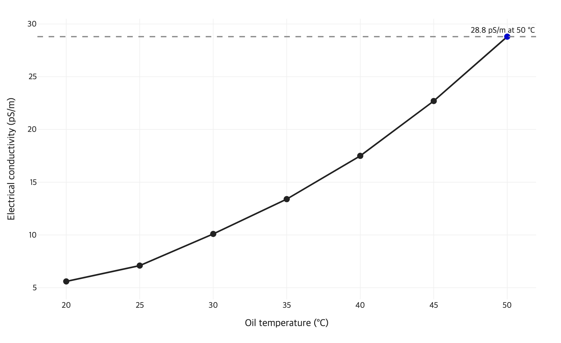
Figure 1. Electrical conductivity of the turbine oil tested by Staudt et al. (2020) between 20 and 50 °C; the 500 pS/m onset level for electrostatic charging is off the scale. Source: Staudt, Duchowski and Leyer, Tribology Transactions, 2020.
Where does turbine oil varnish deposit, and why there?
Turbine oil varnish deposits mostly in the cooler, slower parts of the circuit, because oil that picks up degradation products in hot zones becomes supersaturated when it cools. Most oil breakdown happens in the hottest parts of a system, and soluble varnish turns into deposits in cooler areas until its level falls below what the oil can hold at that temperature (Hong and Jang, 2023).
In steam turbines, varnish plates out on servo valves, which leads to valve sticking, and plugs the sintered metal or fine-screen last-chance filters in the low-flow, colder hydraulic control section, where lower solubility at lower temperature brings it out of solution (STLE, 2013). Deposits also form on mechanical seals, babbitt sleeve bearings, thrust-bearing pads and orifices, and on heat exchanger and reservoir walls, where they reduce heat transfer (STLE, 2013).
Operating pattern matters as much as geometry. Peaking units with frequent starts and stops put more heating and cooling cycles on the oil (STLE, 2016), and idle periods give varnish time to form in cool oil (STLE, 2008). Turbine systems with separate sumps for the turbine and hydraulic sections are reported to suffer far fewer varnish problems than units with a combined sump (STLE, 2008). The deposit location therefore shows where the oil cooled, not always where it degraded.
Conditions that change turbine oil varnish formation
Five varnish pathways run in parallel in a turbine oil system, and each leaves a different combination of trigger, deposit location and test signal. Bulk oxidation depends on average oil temperature and catalysts such as water, air and wear metals. Local thermal degradation, micro-dieseling and electrostatic discharge damage a small volume of oil at very high temperature. Solvency loss does not create degradation products; it decides how many of them stay dissolved as the oil cools. Rows marked inference combine published mechanisms with our own reasoning and have not been tested as a set.
The condition table below decides which mitigation fits the dominant varnish pathway by matching the trigger, the deposit location and a confirming test:
Pathway | Trigger condition | Where deposits appear | Test that confirms it |
|---|---|---|---|
Bulk oxidation | Rate about doubles per 10 °C rise; water, air and wear metals speed it up (STLE, 2016) | Throughout the circuit, heaviest in cool zones (inference) | Falling RULER phenol and amine peaks with falling RPVOT |
Local thermal degradation | Hot bearings or surfaces; thermal degradation above 299 °C (STLE, 2016) | Near the hot spot, then cool low-flow zones (inference) | Rising MPC color while antioxidants stay high (inference) |
Micro-dieseling | Entrained air compressed at pump inlets or loaded bearings | Pumps and loaded bearings (inference); submicron carbonaceous deposits and dark brown varnish (Hong and Jang, 2023) | Long air release time; dark MPC patch (inference) |
Electrostatic discharge | Conductivity below 500 pS/m and filter flux above 0.01 L/min/cm² (Staudt et al., 2020) | Burnt filter media, varnish downstream of filters | Filter element inspection; oil conductivity at cold start (inference) |
Solvency loss in Group II and III oils | Low aromatic content, cool oil, idle periods | Servo valves, last-chance filters, cool hydraulic section | MPC higher after cooling than in a warm filtration (inference) |
The row most often missed is electrostatic discharge: it needs only low-conductivity oil and high flux through a fine filter, conditions common in modern turbine circuits, and it can leave the bulk antioxidant reading high. That reading is our inference from the sources above. In practice two or three pathways usually act together, so the table points to the dominant one rather than the only one.
Which edge cases break the usual turbine oil varnish pattern?
Several edge cases produce turbine oil varnish outside the hot-spot and solvency pattern, and they matter because each needs a different fix.
Antioxidant chemistry is the first. Phenyl alpha naphthylamine (PANA), an aminic antioxidant, gives very high RPVOT values, and a vendor-affiliated expert reported that it can form large amounts of varnish and sludge when it depletes; a turbine oil formulator noted that it is not necessarily a problem in small concentrations combined with phenolics (STLE, 2008).
Incompatible oils are the second. Changing to a Group II oil without testing compatibility with the previous Group I oil can leave decomposed or fresh Group I additives that react with the Group II additives (Hong and Jang, 2023).
Contamination is the third. Preservative and flushing fluids containing metals, typically calcium, can react with acidic components of ashless turbine oils to form an insoluble soap (STLE, 2008).
Ultraviolet light is the fourth. New oil stored outdoors in containers such as polytotes can degrade quickly and contribute to varnish (Hong and Jang, 2023).
Application is the fifth. In paper machine oils, varnish forms mainly by additive hydrolysis rather than oxidative breakdown (STLE, 2016).
Sample handling can also mislead. Membrane patch color darkens with a longer incubation period and lightens when the sample oil is warm or mixed with solvent before filtration, so a warm or solvent-mixed sample risks underestimating varnish potential (Kon et al., 2018).
How do you confirm which varnish pathway is active?
You confirm the active varnish pathway in a turbine oil by trending a bulk test, a deposit test and a pathway-specific check together, then comparing the pattern with the condition table. ASTM D7843-25e1, membrane patch colorimetry (MPC), filters insoluble contaminants from in-service turbine oil onto a patch and reports its color as a ΔE value on the CIELAB scale. The method is not appropriate for dyed oils and serves as a trending tool within a comprehensive condition monitoring program (ASTM D7843-25e1, 2025).
The MPC Δ(a+b) value separates amber-brown varnish patches from black patches with high ΔE caused by soot or high-temperature breakdown products (Pravda et al., 2024). A black patch points toward micro-dieseling or spark damage rather than ordinary oxidation (inference). RULER reads phenolic and aminic peaks separately (ASTM D6971-22, 2022), and problems tend to start once the phenols are gone (STLE, 2008). The ultracentrifuge test spins a sample for 30 minutes at 18,000 rpm and rates agglomerated insolubles from 1 to 8 (Hong and Jang, 2023).
Rising MPC with high RULER and RPVOT values is the signature of a local pathway (inference). Then check local pathways directly: air release time for micro-dieseling (ASTM D3427-26, 2026), and for electrostatic discharge, clicking noises from the filter housing and burnt filter elements (STLE, 2008). Oxidation products that came out of solution at room temperature were soluble at turbine operating temperature (Kon et al., 2018), so comparing a warm and a cooled filtration indicates the soluble precursor load (inference).
What does varnish formation mean for turbine oil selection?
Varnish formation means turbine oil selection should weigh solvency, deposit tendency and electrical behavior alongside oxidation test life, because a long RPVOT or a high antioxidant level does not show how the oil handles the products it forms. RPVOT is not intended to compare the service lives of new oils of different compositions (ASTM D2272-22, 2022).
Ask for deposit-tendency data from tests such as the dry turbine oil oxidation stability test (dry TOST, ASTM D7873-22a), run at 120 °C without water (Hong and Jang, 2023), and for field experience. For Group II base oils, adding small amounts of a polar base oil such as an ester or alkylated naphthalene improves solvency and helps keep varnish precursors dissolved (STLE, 2013).
Oil conductivity had not appeared in any major American or European turbine oil specification as of 2016 (STLE, 2016), so ask for a measured value at operating and cold-start temperature. Pair low-conductivity oils with filter elements that prevent the onset of electrostatic discharge, which a filter maker's technology director described in 2016 as readily achievable (STLE, 2016). Separate turbine and hydraulic oil systems are the ideal plant design, since the worst varnish problems happen in the hydraulic system when the oil cools (STLE, 2008), and good air release reduces micro-dieseling (STLE, 2016).
Lubinpla, an applied AI company that structures technical reasoning for specialty chemicals, can work such a case from a plant's own TDS, SDS, CoA and site history, set out the conditions and evidence, and return one cited document for review, with the engineer approving each step.
Key takeaways
Bulk antioxidant tests measure protection left in the oil, not products already formed at hot spots, sparks or collapsing air bubbles.
Group II and III oils resist oxidation better but dissolve fewer polar degradation products, so precursors drop out sooner in cool zones.
Electrostatic discharge needs only low-conductivity oil and high flux through fine filters; cold starts and flushing are the worst case.
Deposit location shows where the oil cooled. The pathway shows up in MPC color, RULER peaks, air release and filter inspection read together.
Choose turbine oils on deposit tendency, solvency and conductivity as well as oxidation life.
Lubinpla applies this kind of reasoning to your own documents and site history and drafts the document for your review before it goes out.
Sources checked 2026-10-13.
Sources
STLE (Van Rensselar J.). The unvarnished truth about varnish. Tribology & Lubrication Technology, November 2016. https://www.stle.org/files/TLTArchives/2016/11_November/Feature.aspx
STLE (Day L.). Solving varnish problems in gas turbine lubricants. Tribology & Lubrication Technology, January 2008. https://www.stle.org/images/pdf/STLE_ORG/BOK/OM_OA/Additives/Solving%20Varnish%20Problems%20in%20Gas%20Turbine%20Lubricants_tlt%20article_Jan08.pdf
STLE (Whitby R. D.). Varnish deposits from steam turbine oils. Tribology & Lubrication Technology, November 2013. https://www.stle.org/images/pdf/STLE_ORG/BOK/LS/Additives/Varnish%20Deposits%20from%20Steam%20Turbine%20Engine%20Oils_tlt%20article_Nov13.pdf
Hong S.-H., Jang E. K. Varnish formation and removal in lubrication systems: a review. Materials 16(10), 3737, 2023. https://pmc.ncbi.nlm.nih.gov/articles/PMC10222146/
Kon T., Honda T., Sasaki A. Estimation of the oxidative deterioration of turbine oil using membrane patch color. Advances in Tribology, 2020. https://doi.org/10.1155/2020/1708408
Kon T., Honda T., Sasaki A. Influence of solvents, oil temperature, and incubation period on membrane patch color. Tribology Online 13(5), 2018. https://www.jstage.jst.go.jp/article/trol/13/5/13_225/_article
Yano A., Watanabe S., Miyazaki Y., Tsuchiya M., Yamamoto Y. Study on sludge formation during the oxidation process of turbine oils. Tribology Transactions 47(1), 2004. https://doi.org/10.1080/05698190490278985
Staudt J., Duchowski J. K., Leyer S. Prevention of electrostatic charge generation in filtration of low-conductivity oils by surface modification of modern filter media. Tribology Transactions, 2020. https://orbilu.uni.lu/bitstream/10993/42329/1/TT_paper_final%20%28002%29.pdf
Pravda S., Sedenka D., Blata J., Hrabovsky L. Influence of incubation period on membrane patch color for insoluble contaminant measurement in degraded hydraulic oils. Frontiers in Mechanical Engineering, 2024. https://www.frontiersin.org/journals/mechanical-engineering/articles/10.3389/fmech.2024.1366543/full
ASTM International. ASTM D7843-25e1 Standard Test Method for Measurement of Lubricant Generated Insoluble Color Bodies in In-Service Turbine Oils using Membrane Patch Colorimetry. 2025. https://store.astm.org/d7843-25e01.html
ASTM International. ASTM D6971-22 Standard Test Method for Measurement of Hindered Phenolic and Aromatic Amine Antioxidant Content in Non-zinc Turbine Oils by Linear Sweep Voltammetry. 2022. https://store.astm.org/d6971-22.html
ASTM International. ASTM D2272-22 Standard Test Method for Oxidation Stability of Steam Turbine Oils by Rotating Pressure Vessel. 2022. https://store.astm.org/d2272-22.html
ASTM International. ASTM D3427-26 Standard Test Method for Air Release Properties of Hydrocarbon Based Oils. 2026. https://store.astm.org/d3427-26.html
ASTM International. ASTM D7873-22a Standard Test Method for Determination of Oxidation Stability and Insolubles Formation of Inhibited Turbine Oils at 120 °C Without the Inclusion of Water (Dry TOST Method). 2022. https://store.astm.org/d7873-22a.html
Written by the Lubinpla team from the sources listed and checked against them before publication.