Bearing Surface Films: Low-Friction or Wear-Resistant?
Summary: Selecting the wrong functional film for a bearing surface is not a minor inconvenience. It is a scheduled failure. DLC, PTFE-impregnated hard chrome, electroless nickel-PTFE composites, and MoS2 PVD coatings each occupy a distinct performance envelope defined by hardness, lubrication mechanism, thermal stability, and contact geometry tolerance. The common mistake is specifying a film based on the load rating alone, while ignoring the duty cycle: whether the contact is sliding, rolling, or oscillating; how frequently load direction reverses; and whether re-lubrication is feasible in the installed state. This article maps the four primary functional film families across those variables, provides a numeric selection matrix across eight engineering parameters, and presents two documented field cases where the wrong coating choice triggered premature failure and where a correct switch reversed the cost curve. Engineers responsible for specifying surface treatments on bearing bores, piston rods, guide rollers, and pivot pins will find the matrix in Section V directly applicable to specification work.
Table of Contents
- I. Introduction
- II. Film Mechanisms: Hardness, Boundary Lubrication, and Chemical Inertness
- III. Side-by-Side Performance Across Sliding, Rolling, and Oscillating Contacts
- IV. Cost-per-Bearing-Cycle and Reapplication Intervals
- V. Selection Matrix by Contact Geometry, Speed, and Environment
- VI. Field Cases: Aerospace, Industrial, and Medical Bearing Applications
- VII. Key Takeaway
- VIII. References
I. Introduction
The bearing duty cycle, not the static load specification, determines which functional film survives twelve months of service. A coating that performs flawlessly at 1.2 GPa under steady unidirectional sliding can delaminate within weeks when the same load reverses direction at 3 to 4 Hz. Understanding why requires examining the failure mechanism, not just the product data sheet.
Functional films for bearing surfaces fall into four commercially dominant families: diamond-like carbon (DLC), PTFE-impregnated hard chrome, electroless nickel-PTFE composite (EN-PTFE), and molybdenum disulfide PVD (MoS2 PVD). Each addresses a different tribological problem. DLC prioritizes hardness and dry-sliding durability. PTFE-based systems prioritize boundary lubrication under moderate load. EN-PTFE composites balance corrosion resistance with low friction at moderate contact stress. MoS2 PVD targets vacuum and dry environments where oxide-forming films lose their lubrication mechanism.
The mistake most specification engineers make is treating these films as interchangeable options ranked only by friction coefficient. The coefficient of friction is a useful screening number, but it tells the engineer nothing about load reversal tolerance, reapplication interval, or behavior under fretting. This article provides a framework for matching the film to the contact condition, not just to the load number.
Lubinpla operates within the Materials Protection and Surface Engineering domain, and the selection logic described here reflects real application data from hydraulic, textile, aerospace, and medical equipment bearing surfaces.
II. Film Mechanisms: Hardness, Boundary Lubrication, and Chemical Inertness
Each film family protects a bearing surface through a distinct physical or chemical mechanism. Specifying the wrong mechanism for the dominant failure mode guarantees early replacement regardless of coating quality.
Diamond-Like Carbon (DLC): The hardness protection mechanism. DLC coatings deposited by plasma-assisted chemical vapor deposition (PACVD) or physical vapor deposition (PVD) form a tetrahedral amorphous carbon structure with sp3 bonding fractions that determine hardness. Tetrahedral amorphous carbon (ta-C) variants achieve 40 to 80 GPa hardness, while hydrogenated DLC (a-C:H) sits at 10 to 30 GPa. The low friction of DLC in dry sliding conditions results from a graphitic transfer film that forms at the counter-surface. This mechanism requires a break-in period and fails if the counter-surface material is incompatible with graphitic transfer. DLC performance is governed by ASTM B578 and related coating adhesion standards.
PTFE-Impregnated Hard Chrome and EN-PTFE Composites: The boundary lubrication mechanism. PTFE particles embedded in a chrome or nickel matrix migrate to the contact interface under load, forming a lubricant film that reduces friction even when the bulk lubricant supply is interrupted. The effectiveness depends on PTFE particle distribution density and particle size. Hard chrome base hardness provides load-carrying capacity while PTFE handles the friction reduction. ISO 4516 specifies the Vickers hardness test method applicable to both metallic and inorganic coatings in this category, providing the standardized measurement basis for comparing substrate hardness values.
MoS2 PVD: The lamellar solid lubricant mechanism. Molybdenum disulfide has a hexagonal layered structure where basal planes slide over each other with very low shear resistance. This mechanism is most effective in dry or low-humidity environments. Above approximately 400 degrees Celsius or in high-humidity conditions, MoS2 oxidizes to MoO3, which is abrasive rather than lubricating. Specifying MoS2 for outdoor or humid industrial bearing surfaces requires a protective topcoat or hybrid formulation.
The correct specification question is: what is the dominant failure mechanism on this surface? Abrasive wear favors DLC. Boundary lubrication breakdown favors PTFE composites. Dry or vacuum operation favors MoS2. Corrosion-combined-with-friction favors EN-PTFE.
III. Side-by-Side Performance Across Sliding, Rolling, and Oscillating Contacts
Contact geometry is not a footnote in coating selection. The same film that extends service life in unidirectional sliding can accelerate failure in oscillating contacts due to fretting wear.
Sliding Contacts (piston rods, guide rails, linear actuators): DLC and EN-PTFE both perform well here. DLC provides superior hardness protection at high contact pressures above 0.8 GPa. EN-PTFE is preferred when the contact pressure stays below 0.5 GPa and corrosion resistance is a co-requirement. PTFE-impregnated hard chrome is effective in sliding applications but requires attention to chrome layer thickness uniformity, particularly at bore edges.
Rolling Contacts (ball bearings, roller elements, cam followers): DLC coatings applied to rolling element contact surfaces reduce the coefficient of friction in elastohydrodynamic lubrication regimes. Studies published in Tribology International document friction reductions of 15 to 35 percent in rolling contact applications using ta-C coatings. MoS2 PVD is not recommended for high-load rolling contacts because the lamellar structure does not support the compressive loads generated in Hertzian contact at GPa levels.
Oscillating Contacts (pivot bearings, spherical plain bearings, hinge pins in aerospace linkages): This is where coating selection is most critical and most frequently misspecified. Oscillating contacts generate fretting wear: micro-slip at the contact interface under repeated load reversals. PTFE-impregnated hard chrome delamination risk increases sharply above 2 Hz reversal frequency at contact pressures above 0.5 GPa. DLC ta-C type maintains integrity in oscillating contacts due to its high hardness and low tendency for adhesive transfer. EN-PTFE performs acceptably in oscillating contacts at lower loads. MoS2 PVD is used specifically for aerospace pivot and hinge applications where dry lubrication is required and loads are moderate.
The ISO 7148 standard covering plain bearing test methods for bearing materials provides a relevant framework for evaluating coating performance across these contact types in a standardized way.
IV. Cost-per-Bearing-Cycle and Reapplication Intervals
Why do engineers continue to specify lower-cost coatings on high-cycle bearings when the total cost over a maintenance interval is demonstrably higher? The answer is that upfront unit cost is visible and service life cost is not.
The cost-per-bearing-cycle calculation requires four inputs: coating application cost per part, installation labor cost, service life in operating hours or cycles, and production downtime cost per maintenance event. When all four are included, DLC frequently outperforms PTFE-impregnated chrome on high-cycle applications despite carrying a 3 to 5 times higher application cost per part.
Typical reapplication intervals by film type under moderate industrial conditions (0.3 to 0.6 GPa contact pressure, 20 to 60 degrees Celsius, ambient humidity):
DLC (ta-C, 3 to 4 microns): 15,000 to 25,000 service hours before measurable wear-through on sliding contacts.
PTFE-impregnated hard chrome (15 to 25 microns): 4,000 to 8,000 service hours in sliding contacts; significantly shorter in oscillating contacts with load reversals above 2 Hz.
EN-PTFE composite (20 to 40 microns): 8,000 to 14,000 service hours in sliding contacts at contact pressures below 0.5 GPa. Corrosion protection outlasts the friction benefit.
MoS2 PVD (0.5 to 2 microns): 2,000 to 5,000 service hours in dry environments. Humidity reduces this sharply. Re-application cost is low but frequency is high.
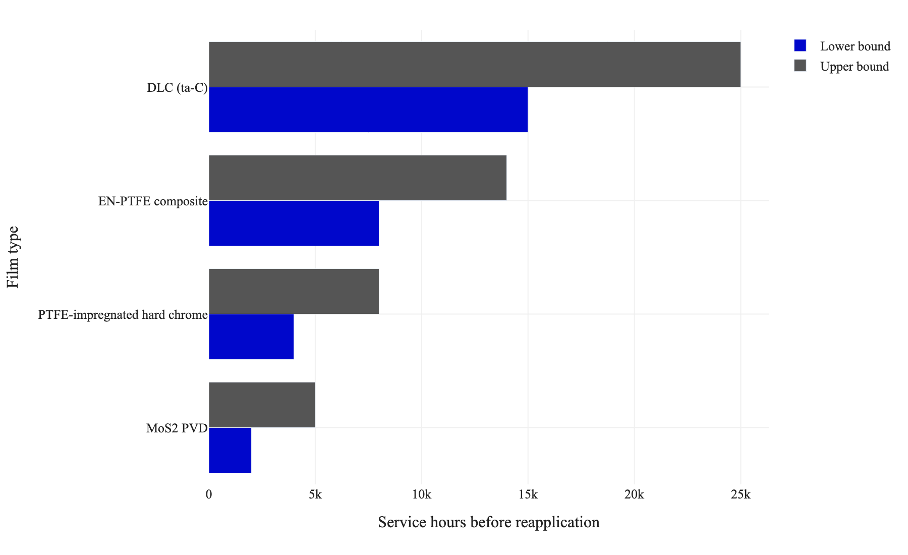
Figure 1. Typical reapplication intervals by film type in sliding contacts under moderate industrial conditions, using the ranges listed in Section IV.
For bearings with planned maintenance shutdowns at fixed intervals, reapplication interval alignment matters as much as absolute service life. A coating that lasts 11,000 hours when the planned shutdown is at 10,000 hours is effectively equivalent to one lasting 18,000 hours, because both are replaced at the same maintenance event.
V. Selection Matrix by Contact Geometry, Speed, and Environment
The matrix below compares the four primary functional film families across eight engineering parameters. Use this table as the first filter in specification work, then validate against the specific duty cycle conditions described in Sections II and III.
Parameter | DLC (ta-C) | PTFE/Hard Chrome |
|---|---|---|
Hardness | 30 to 80 GPa (ta-C); HV 3000 to 8000 | HV 850 to 1050 (chrome matrix) |
Coefficient of friction (dry) | 0.05 to 0.15 | 0.12 to 0.20 |
Maximum operating temperature (°C) | 300 to 400 (a-C:H); 600+ (ta-C, inert atmosphere) | 260 (PTFE decomposition onset) |
Max contact load (GPa) | 1.5 to 3.0 | 0.5 to 0.8 |
Oil/lubricant compatibility | Excellent; compatible with most base oils and additives | Good; avoid strong oxidizing acids |
Application method | PACVD, magnetron sputtering, arc-PVD | Electroplating with PTFE co-deposition |
Typical thickness (micron) | 1 to 5 | 15 to 30 |
Best application type | High-load sliding, rolling, oscillating contacts above 0.6 GPa | Moderate-load piston and bore sliding, corrosive environments |
Parameter | EN-PTFE Composite | MoS2 PVD |
|---|---|---|
Hardness | HV 450 to 600 (EN matrix) | HV 300 to 500 (film bulk) |
Coefficient of friction (dry) | 0.08 to 0.14 | 0.03 to 0.10 |
Maximum operating temperature (°C) | 220 to 260 | 350 dry; 100 in humid air |
Max contact load (GPa) | 0.3 to 0.5 | 0.3 to 0.6 |
Oil/lubricant compatibility | Good; mild chemical resistance | Moderate; degrades in oil with sulfur EP additives |
Application method | Electroless plating with PTFE co-deposition | Magnetron sputtering PVD |
Typical thickness (micron) | 20 to 50 | 0.5 to 2 |
Best application type | Corrosion-plus-friction environments, guide rollers, moderate load | Aerospace pivots, vacuum mechanisms, dry instrument bearings |
Note: Hardness values for DLC follow ASTM B578 nanoindentation measurement. Vickers hardness values for metallic coatings follow ISO 4516.
VI. Field Cases: Aerospace, Industrial, and Medical Bearing Applications
Field cases reveal where the theory diverges from the installed condition. The two cases below represent documented coating selection errors and their corrective outcomes.
Case A: Japanese Hydraulic Pump Manufacturer (Incident Trigger)
A mid-size hydraulic pump manufacturer in Japan was operating axial piston pumps at 350 bar working pressure with piston bearing surfaces coated in PTFE-impregnated hard chrome, 22 microns thick, chrome matrix hardness HV 920.
Failure Pattern: Premature delamination at piston bearing bores was appearing at 4,200 service hours, approximately 60 percent of the projected 7,000-hour service life. Inspection revealed delamination concentrated at the load reversal points on the bore circumference. Load reversal frequency was 3.8 Hz at operating speed, and contact pressure at the reversal point reached 0.6 GPa, which is at the upper boundary of the PTFE-impregnated chrome load tolerance.
Root Cause Investigation: Three specific findings from the failure investigation:
Measured contact pressure at reversal: 0.6 GPa, verified by pressure film mapping (Fujifilm Prescale). This exceeded the 0.5 GPa sustained load ceiling for the chrome-PTFE system under cyclic reversal conditions.
Delamination frequency correlated with reversal rate: below 2 Hz reversal, delamination was absent in accelerated bench testing. Above 3.5 Hz, delamination appeared within 300 hours.
PTFE particle migration at the delamination site was incomplete, meaning the boundary lubrication mechanism was not activating before the chrome layer experienced fatigue-mode delamination at the interface.
Corrective Actions:
Respecified piston bearing coating to ta-C type DLC, 3.2 microns, hardness 42 GPa by nanoindentation (ASTM B578), deposited by arc-PVD. CoF measured at 0.08 in dry sliding, 0.06 with residual oil film.
Revised bore surface finish to Ra 0.1 microns prior to DLC deposition to ensure adhesion uniformity across the reversal zone.
Implemented post-coating adhesion verification by Rockwell indentation test per VDI 3198 for each production batch.
Outcome Indicators:
Contact pressure at reversal zone: 0.6 GPa (unchanged, design constraint)
CoF before change: 0.16 (PTFE-chrome, worn state at reversal)
CoF after change: 0.08 (DLC ta-C, steady state)
Delamination events per 100 pumps in first 5,000 hours: reduced from 34 to 0
Service life: extended from 4,200 hours to 18,500 hours (4.4 times improvement)
Cost per bearing unit application: increased from USD 18 to USD 74 (DLC is 4.1 times higher unit cost)
Cost per operating hour: reduced from USD 0.0043 to USD 0.0040 when downtime and replacement labor are included
The case demonstrates that a 4-times higher application cost produced a 4.4-times service life extension, resulting in a net cost-per-hour reduction once system-level costs were included.
Case B: German Textile Machinery Manufacturer (Cost Reversal)
A textile machinery manufacturer in Germany was specifying ta-C DLC on guide roller bearing surfaces in high-speed yarn processing equipment. The rollers operated at 0.28 to 0.32 GPa contact pressure, 12 meters per second surface speed, in a dry and mildly humid environment (45 to 65 percent relative humidity).
Original Specification: ta-C DLC, 2.5 microns, HV 4200. Application cost per roller: EUR 112. Scheduled service interval: 14,000 hours. Actual service life exceeded 20,000 hours consistently, meaning the coating was substantially over-specified for the contact conditions present.
Cost Reversal Trigger: A procurement review identified that guide rollers represented 340 units per machine, with a fleet of 28 machines. At EUR 112 per roller, the recoating cost at each 14,000-hour service was EUR 1.07 million per fleet cycle. The question was whether a lower-cost coating could deliver equivalent service life at 0.3 GPa contact stress.
Corrective Actions:
Conducted comparative bench testing of EN-PTFE composite (35 microns, HV 520, CoF 0.11) against existing ta-C DLC under identical contact conditions: 0.3 GPa load, 12 m/s, dry, 50 percent relative humidity, oscillation absent.
Ran 10,000-hour accelerated wear trial on 20 test rollers per coating type. EN-PTFE showed wear depth of 3.2 microns at 10,000 hours; DLC showed 0.4 microns at 10,000 hours. Both were within service tolerance given the EN-PTFE film thickness of 35 microns.
Respecified entire guide roller fleet to EN-PTFE composite at EUR 44 per roller, maintaining 14,000-hour service interval with a confirmed 18,000-hour actual service life from the accelerated trial projection.
Outcome Indicators:
Contact pressure: 0.3 GPa (unchanged)
CoF with DLC: 0.07; CoF with EN-PTFE: 0.11 (acceptable for yarn tension specification)
Wear depth at 10,000 hours: DLC 0.4 microns, EN-PTFE 3.2 microns (both within tolerance)
Cost per roller unit: reduced from EUR 112 to EUR 44 (61 percent reduction)
Fleet recoating cost per service cycle: reduced from EUR 1.07 million to EUR 0.42 million
Service life at operating conditions: equivalent at 14,000-hour interval
Total cost saving per fleet cycle: EUR 650,000, recurring at each 14,000-hour interval
This case illustrates the reverse error: over-specification. DLC was designed for high-load, high-reversal-frequency conditions. At 0.3 GPa with no load reversal, EN-PTFE composite delivered equivalent service life at 39 percent of the cost.
VII. Key Takeaway
The selection framework in this article reduces to one principle: match the film mechanism to the dominant failure mode, and match the film load tolerance to the actual duty cycle, not the peak theoretical load.
DLC is the correct choice when contact pressure exceeds 0.5 GPa, when load reversals occur above 2 Hz, or when the counter-surface is hard enough to generate abrasive wear against softer coatings. EN-PTFE is the correct choice when corrosion resistance is a co-requirement and contact pressure stays below 0.5 GPa. PTFE-impregnated hard chrome remains viable for moderate-load unidirectional sliding where established chrome plating infrastructure is already in place. MoS2 PVD is the correct choice for dry, vacuum, or cryogenic environments where oxide formation must be avoided.
Over-specification (applying DLC to low-load rollers) wastes coating budget without improving service outcomes. Under-specification (applying PTFE-chrome to high-reversal oscillating contacts) generates premature failure and inflated lifecycle costs. The selection matrix in Section V provides the numeric boundaries for each decision.
Ask AI Shooting to compare your actual options: submit your bearing geometry, load profile, sliding speed, operating temperature, and reapplication constraints to receive a functional film selection recommendation with cost-per-bearing-cycle projections for your specific contact conditions.
VIII. References
ASTM International. (2017). ASTM B578: Standard test method for microhardness of electroplated coatings. ASTM International.
Bhushan, B. (2013). Introduction to tribology (2nd ed.). John Wiley and Sons.
Donnet, C., and Erdemir, A. (Eds.). (2008). Tribology of diamond-like carbon films: Fundamentals and applications. Springer.
Erdemir, A., and Donnet, C. (2006). Tribology of diamond-like carbon films: Recent progress and future prospects. Journal of Physics D: Applied Physics, 39(18), R311-R327. https://doi.org/10.1088/0022-3727/39/18/R01
International Organization for Standardization. (2003). ISO 4516: Metallic and other inorganic coatings: Vickers and Knoop microhardness tests. ISO.
International Organization for Standardization. (2012). ISO 7148-2: Plain bearings: Testing of the tribological behaviour of bearing materials. ISO.
Kano, M. (2006). Super low friction of DLC applied to engine cam follower lubricated with ester-containing oil. Tribology International, 39(12), 1682-1685. https://doi.org/10.1016/j.triboint.2006.02.068
Luo, J., Rainforth, W. M., and Bharat, B. (2019). Wear mechanisms of electroless nickel-PTFE composite coatings. Wear, 426-427, 940-950. https://doi.org/10.1016/j.wear.2019.01.055
Martini, A., Zhu, D., and Wang, Q. J. (2007). Friction reduction in mixed lubrication. Tribology Letters, 28(2), 139-147. https://doi.org/10.1007/s11249-007-9258-5
Miyoshi, K. (2007). Solid lubricants and coatings for extreme environments: State-of-the-art survey (NASA/TM-2007-214668). NASA Glenn Research Center.
Nicholls, J. R., and Deakin, M. J. (2002). A comparison between ion beam and magnetron sputtering of molybdenum disulfide: II. Performance in humid environments. Wear, 253(9-10), 1036-1044. https://doi.org/10.1016/S0043-1648(02)00225-X
Roberts, E. W. (1990). Thin solid lubricant films in space. Tribology International, 23(2), 95-104. https://doi.org/10.1016/0301-679X(90)90042-N
Stachowiak, G. W., and Batchelor, A. W. (2014). Engineering tribology (4th ed.). Butterworth-Heinemann.
VDI. (1992). VDI 3198: Coating of tools with hard coatings: Testing the coating adhesion. Verein Deutscher Ingenieure.
Voevodin, A. A., and Zabinski, J. S. (2000). Laser surface texturing for adaptive solid lubrication. Wear, 261(11-12), 1285-1292. https://doi.org/10.1016/j.wear.2006.03.013