Choosing Sealants for Chemical-Resistant Joints in Process Equipment
Summary: Sealant selection for chemical process equipment requires matching sealant chemistry to the specific chemical exposure, temperature range, joint movement, and substrate material. Wrong selection leads to leaks, contamination, or safety incidents. This article provides a chemical resistance hierarchy for major sealant families (silicone, fluorosilicone, polysulfide, fluoroelastomer, PTFE-based), a condition matrix organized by chemical exposure type, detailed testing protocols referencing ASTM and ISO standards, environmental degradation analysis, and field diagnostic guidance for experienced plant engineers.
Table of Contents
I. Why Sealant Selection in Process Equipment Is Critical
II. Real-World Failure Scenarios: Lessons from the Field
III. Chemical Resistance Hierarchy by Sealant Family
IV. Chemical Resistance Data: Specific Chemicals and Concentrations
V. Condition Matrix: Chemical Exposure to Sealant Chemistry
VI. Environmental Degradation Factors
VII. Evaluating Sealant Compatibility: Testing Protocols and Standards
VIII. Field Diagnostic Tips for Sealant Failure Analysis
IX. Key Takeaway
X. References
I. Why Sealant Selection in Process Equipment Is Critical
Process equipment joints, including flanges, expansion joints, access panels, and pipe penetrations, operate under continuous exposure to aggressive chemicals, elevated temperatures, and mechanical movement from thermal expansion and vibration. A sealant failure in these environments does not simply cause a leak. It can cause chemical contamination of products, environmental release of hazardous materials, equipment corrosion from seal bypass, and in extreme cases, fire or explosion from flammable fluid release.
The Selection Challenge
The challenge is that no single sealant chemistry resists all chemicals at all temperatures. Silicone sealants offer excellent temperature resistance but fail rapidly in hydrocarbon solvents. Polysulfide sealants resist fuels and solvents but degrade in strong oxidizing acids. Each sealant family has a distinct chemical resistance profile, and selecting the wrong one guarantees failure.
This reality creates a selection problem that compounds as process conditions become more complex. A single piece of equipment may have flanged joints exposed to sulfuric acid on one side and hydrocarbon vapors on the other. The sealant that protects against the acid may swell and fail when the hydrocarbon migrates through. Field engineers routinely encounter situations where a sealant performs well during commissioning but degrades within months because the actual service environment includes chemical exposures not captured in the original specification.
Failure Consequences
Gasket and seal failure is one of the most preventable causes of unplanned downtime in process plants, yet it continues to occur across refineries, chemical processing facilities, and power generation operations worldwide. Industry estimates suggest that seal and gasket failures account for a significant share of unplanned process equipment shutdowns. The cost per incident typically ranges from USD 5,000 for minor leak repairs to over USD 100,000 for contamination events requiring product disposal, equipment decontamination, and regulatory reporting.
Beyond direct repair costs, sealant failures trigger cascade effects. A leaking flange on a sulfuric acid line may corrode adjacent carbon steel supports, requiring structural repairs that dwarf the original seal replacement cost. A failed sealant on a fuel storage tank access panel may allow vapor migration into utility corridors, creating confined-space hazards that shut down entire sections of a facility. In pharmaceutical and food processing, a single sealant failure that allows chemical cross-contamination can result in batch rejection costs exceeding USD 500,000, not counting the downstream impact on customer relationships and regulatory standing.
II. Real-World Failure Scenarios: Lessons from the Field
Understanding how sealants fail in actual service conditions is more instructive than any chemical resistance chart. The following scenarios represent common failure patterns that experienced plant engineers encounter.
Scenario 1: Silicone Sealant on a Diesel Transfer Line Flange
A maintenance team applied a general-purpose RTV silicone sealant to a flanged connection on a diesel fuel transfer line after the original gasket was unavailable during a weekend shutdown. The silicone cured properly and the joint tested leak-free at startup. Within six weeks, operators reported weeping at the flange. Inspection revealed that the silicone had swelled to roughly twice its original volume and had lost adhesion to the flange face. The silicone's polydimethylsiloxane (PDMS) backbone has an open molecular structure that allows small hydrocarbon molecules, particularly the aromatic fraction in diesel, to diffuse into the polymer matrix. The resulting volume swell weakens the material until it can no longer maintain a compression seal. This is one of the most commonly repeated sealant errors in plant maintenance: reaching for the familiar silicone tube when the application demands a fuel-resistant chemistry like fluorosilicone or polysulfide.
Scenario 2: Polysulfide Sealant Exposed to Concentrated Nitric Acid Splash
In a fertilizer production facility, polysulfide sealant was used on an access panel located near a nitric acid dosing station. The panel was not directly in the acid stream, but periodic splash and vapor exposure was routine. After approximately four months, the sealant exhibited surface hardening, cracking, and brown discoloration. Polysulfide's sulfur-sulfur bonds in the polymer backbone are vulnerable to attack by strong oxidizing agents. Nitric acid, even as dilute splash or concentrated vapor, oxidizes the sulfide linkages, causing chain scission and progressive embrittlement. The correct selection for oxidizing acid environments is PTFE-based sealant or, for limited concentrations, specialty perfluoroelastomer (FFKM) formulations.
Scenario 3: Fluoroelastomer Sealant Failure in Ketone Service
A chemical processing plant specified a standard fluoroelastomer (FKM, Viton A-type) sealant for joints on a methyl ethyl ketone (MEK) storage vessel. The FKM was selected based on its broad chemical resistance reputation. Within three months, the sealant had softened dramatically and lost dimensional stability. Standard FKM grades based on vinylidene fluoride and hexafluoropropylene copolymers are susceptible to attack by low-molecular-weight ketones, esters, and certain amines. These polar solvents penetrate the fluoropolymer matrix and cause plasticization, softening, and eventual cohesive failure. The appropriate choice for ketone service is polysulfide sealant or PTFE-based products. Specialty FKM grades (such as Viton GLT or base-resistant types) may offer improved performance, but standard FKM should be flagged as incompatible with ketones in any selection guide.
Scenario 4: Thermal Cycling Fatigue on an Expansion Joint
A petrochemical facility used a high-durometer fluoroelastomer sealant on a pipe expansion joint that experienced daily temperature cycling between ambient (approximately 25 degrees Celsius) and 180 degrees Celsius during batch operations. The joint saw plus or minus 8 mm of cyclical movement. After about 200 thermal cycles, the sealant developed radial cracks originating from the adhesion interface. Thermal cycling imposes fatigue stress on sealant materials through repeated expansion and contraction. High-durometer (high-hardness) sealants have lower elongation at break and cannot absorb the cumulative strain. For expansion joints with significant thermal cycling, a lower-durometer formulation with higher elongation capability, such as fluorosilicone or a flexible FKM grade, is required. The sealant's fatigue resistance under cyclic conditions is at least as important as its static chemical resistance.
III. Chemical Resistance Hierarchy by Sealant Family
Understanding each sealant family's chemistry explains its resistance profile.
Figure 1. Chemical Resistance Heatmap by Sealant Family
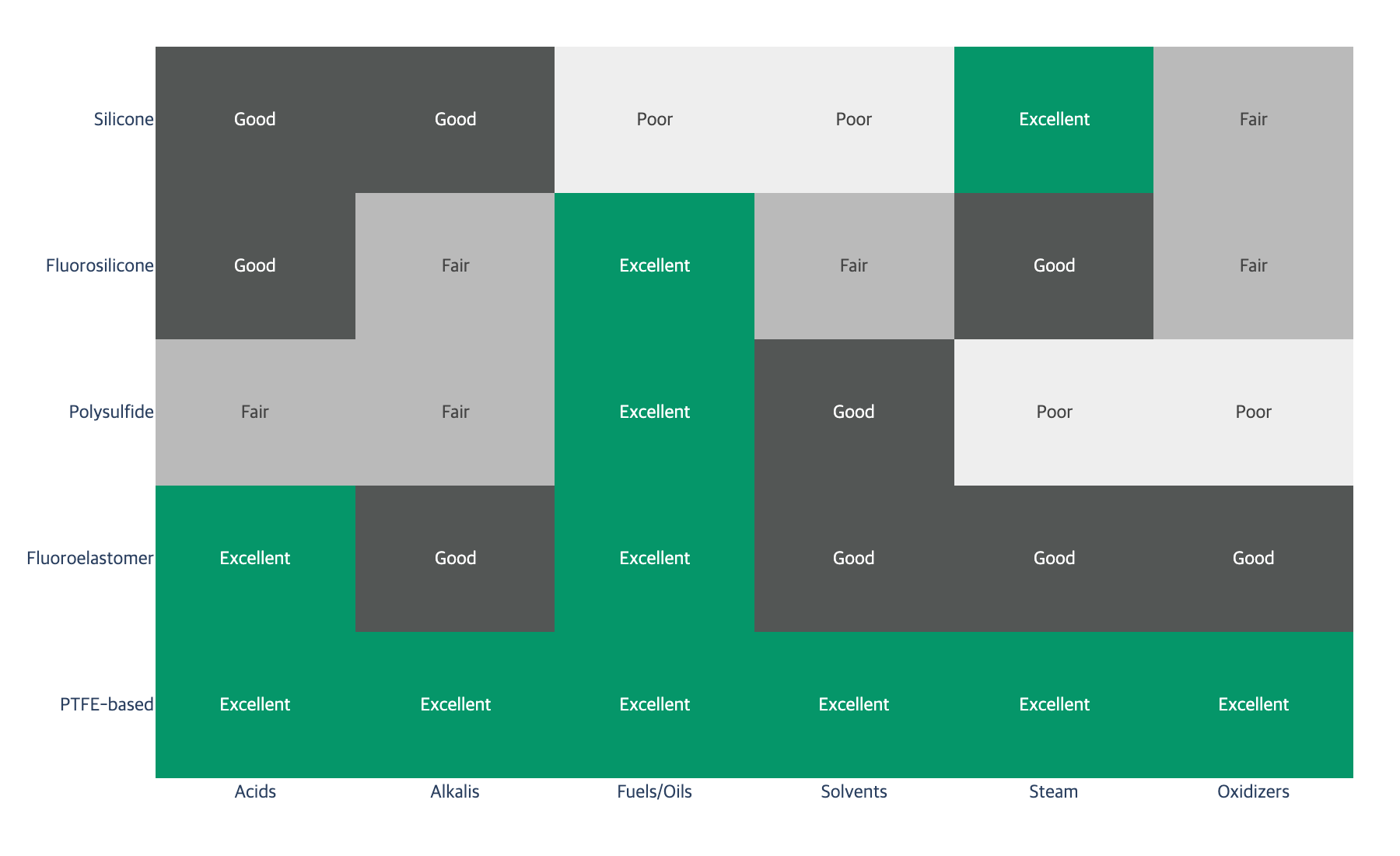
Figure 1b. Sealant Family Chemical Resistance Overview
Sealant Family | Acids | Alkalis | Fuels/Oils | Solvents (Ketones, Esters) | Temperature Range | Joint Movement |
|---|---|---|---|---|---|---|
Silicone (PDMS) | Good (dilute) | Good | Poor | Poor | -60 to 250C | High (25-50%) |
Fluorosilicone (FVMQ) | Good | Fair | Excellent | Fair | -50 to 200C | High (20-40%) |
Polysulfide | Fair | Fair | Excellent | Good | -40 to 120C | Medium (15-25%) |
Fluoroelastomer (FKM/Viton) | Excellent | Good | Excellent | Good | -20 to 200C | Low (10-15%) |
PTFE-based | Excellent | Excellent | Excellent | Excellent | -200 to 260C | Very low (5%) |
Polyurethane | Poor | Poor | Good | Poor | -40 to 80C | High (25-50%) |
PTFE-based sealants offer the broadest chemical resistance because the carbon-fluorine bond is one of the strongest in organic chemistry (bond energy approximately 485 kJ/mol), providing near-universal chemical inertness. However, PTFE sealants have very low joint movement capability due to cold flow under compression and are primarily used as thread sealants or gasket materials rather than flexible joint sealants.
Why Silicone Fails in Hydrocarbon Service
Silicone (polydimethylsiloxane, PDMS) has a relatively open molecular structure that allows small hydrocarbon molecules to diffuse into the polymer matrix, causing swelling that weakens the material and eventually leads to cohesive failure. Fluorosilicone replaces some methyl groups with trifluoropropyl groups, which resist hydrocarbon penetration while maintaining silicone's temperature flexibility.
In quantitative terms, standard silicone immersed in ASTM Reference Fuel B (a 70/30 blend of isooctane and toluene) typically exhibits volume swell exceeding 100 percent within 72 hours at room temperature. Fluorosilicone under the same conditions typically shows volume swell below 10 percent. This difference illustrates why the fluorine substitution is critical for any application involving hydrocarbon contact.
Why Polysulfide Excels in Fuel Service
Polysulfide sealants owe their fuel resistance to the sulfur-sulfur bonds in the polymer backbone, which create a polar structure that resists penetration by nonpolar hydrocarbon molecules. This chemistry has made polysulfide the standard sealant for aircraft integral fuel tanks for decades. Products such as PPG PR-1422 and PR-1440 are widely used across the aviation industry for sealing fuel tanks, fuselage joints, fillets, and structural seams, providing proven resistance to Jet A, Jet A-1, and avgas fuels. The cured sealant retains elastomeric properties after prolonged fuel immersion, and polysulfide formulations for aerospace can endure temperatures ranging from approximately -51 degrees Celsius to 121 degrees Celsius while remaining flexible enough to absorb vibration and joint movement during flight.
FKM Grade Selection Matters
Not all fluoroelastomers are created equal. The chemical resistance of FKM varies significantly by grade, determined by the monomer composition and fluorine content. Higher fluorine content generally provides better chemical resistance but reduces low-temperature flexibility:
FKM-A (66% fluorine, e.g., Viton A): General-purpose grade, good resistance to fuels, oils, and many acids. Vulnerable to ketones, esters, and amines.
FKM-B (68% fluorine, e.g., Viton B): Better acid resistance, specified for gaskets sealing mineral acids such as sulfuric acid. Can be formulated with peroxide cure systems to resist strong acids, hot water, and steam.
FKM-F (70% fluorine, e.g., Viton F): Can be formulated to resist concentrated aqueous inorganic acids, hot water, and steam.
FKM-G (e.g., Viton G): Contains substantially more fluorine than other grades. Recommended for hot concentrated sulfuric acid service.
This grade hierarchy means that specifying "FKM" without identifying the grade is insufficient for chemical process applications. A sealant selection that stops at the family level will miss critical compatibility gaps.
IV. Chemical Resistance Data: Specific Chemicals and Concentrations
The overview table in Section III provides a general guide, but field engineers need resistance data at specific concentrations and temperatures. The following table provides more granular information for commonly encountered process chemicals.
Table 1. Detailed Chemical Resistance by Sealant Family
Chemical | Concentration | Temp (C) | Silicone | Fluorosilicone | Polysulfide | FKM | PTFE |
|---|---|---|---|---|---|---|---|
Sulfuric acid | 10% | 25 | Fair | Fair | Poor | Good | Excellent |
Sulfuric acid | 50% | 25 | Poor | Poor | Not recommended | Good (FKM-B) | Excellent |
Sulfuric acid | 96% | 25 | Not recommended | Not recommended | Not recommended | Fair (FKM-G only) | Excellent |
Hydrochloric acid | 10% | 25 | Fair | Fair | Poor | Good | Excellent |
Hydrochloric acid | 37% | 25 | Poor | Poor | Not recommended | Fair | Excellent |
Sodium hydroxide | 10% | 25 | Good | Fair | Fair | Good | Excellent |
Sodium hydroxide | 50% | 60 | Fair | Poor | Poor | Fair | Excellent |
Diesel fuel | neat | 25 | Not recommended | Good | Good | Excellent | Excellent |
Toluene | neat | 25 | Not recommended | Fair | Fair | Good | Excellent |
Methyl ethyl ketone | neat | 25 | Not recommended | Poor | Good | Not recommended | Excellent |
Acetone | neat | 25 | Not recommended | Poor | Fair | Not recommended | Excellent |
Hydrogen peroxide | 30% | 25 | Poor | Poor | Not recommended | Fair (FFKM preferred) | Excellent |
Ethanol | neat | 25 | Good | Good | Good | Good | Excellent |
Acetic acid | 10% | 25 | Fair | Fair | Fair | Good | Excellent |
Ammonia (aqueous) | 10% | 25 | Fair | Poor | Poor | Not recommended | Excellent |
Ratings key: Excellent = less than 5% volume swell and minimal property change after 28-day immersion. Good = 5-10% volume swell with acceptable property retention. Fair = 10-25% volume swell, suitable only for intermittent or splash exposure. Poor = greater than 25% volume swell or significant property degradation. Not recommended = rapid degradation, failure likely within days to weeks.
Table 2. Temperature Impact on Chemical Resistance
These temperature derating factors illustrate how elevated temperature accelerates chemical attack. The Arrhenius relationship provides a useful approximation: for many polymer-chemical interactions, each 10 degrees Celsius increase in temperature roughly doubles the degradation rate.
Service Temperature | Derating Factor | Practical Impact |
|---|---|---|
25C (baseline) | 1.0x | Published resistance data applies |
50C | 2-4x degradation rate | "Good" ratings may drop to "Fair" |
80C | 8-16x degradation rate | Only "Excellent" rated pairings remain reliable |
120C | 50-100x degradation rate | Verify with immersion testing at actual temperature |
150C+ | 200x+ degradation rate | PTFE or specialty FFKM only for aggressive chemicals |
This is why published chemical resistance charts, which are typically generated from room-temperature immersion data, can be dangerously misleading for elevated-temperature service. A sealant rated "good" for dilute sulfuric acid at 25 degrees Celsius may exhibit rapid failure at 80 degrees Celsius. Field engineers should treat room-temperature compatibility data as a starting point, not a specification.
V. Condition Matrix: Chemical Exposure to Sealant Chemistry
Selecting by Primary Chemical Exposure
Chemical Exposure | Recommended Sealant | Alternative | Avoid |
|---|---|---|---|
Dilute mineral acids (HCl, H2SO4 below 30%) | Fluoroelastomer (FKM-B) | PTFE-based | Polyurethane, polysulfide |
Concentrated acids (above 70%) | PTFE-based only | Fluoroelastomer (FKM-G, limited grades) | All elastomeric sealants |
Alkalis (NaOH, KOH below 50%) | Silicone or fluoroelastomer | PTFE-based | Polysulfide |
Fuels and petroleum products | Fluorosilicone or polysulfide | Fluoroelastomer | Standard silicone |
Aromatic solvents (toluene, xylene) | Fluoroelastomer (FKM-A or higher) | PTFE-based | Silicone, polyurethane |
Ketones and esters | Polysulfide or PTFE-based | Specialty fluoroelastomer (base-resistant type) | Standard FKM, silicone |
Steam (above 150C) | Silicone (high-temp grade) | PTFE-based | Polyurethane, polysulfide |
Oxidizing agents (H2O2, HNO3) | PTFE-based | Specialty FFKM (perfluoroelastomer) | Polysulfide, polyurethane |
Mixed chemical exposure (acid + hydrocarbon) | PTFE-based | FFKM (where flexibility needed) | Any single-chemistry elastomer |
Temperature Modifiers
Chemical resistance data is typically reported at room temperature (approximately 23 degrees Celsius per ASTM test conditions). At elevated temperatures, chemical attack rates increase and sealant physical properties change. As noted in the derating table above, every 10 degrees Celsius increase in temperature approximately doubles the chemical degradation rate following the Arrhenius relationship. A sealant rated for "good" resistance at 25 degrees Celsius may show "fair" or "poor" performance at 80 degrees Celsius. Always verify sealant compatibility at the actual service temperature, not just at room temperature.
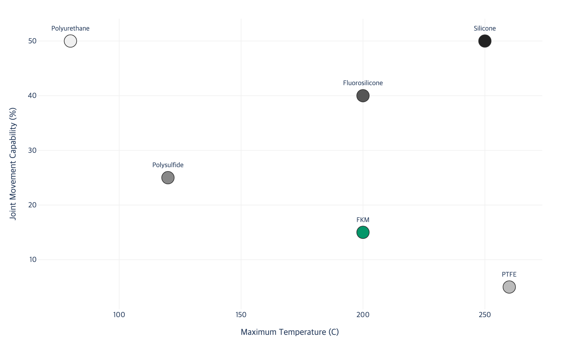
Figure 2. Temperature Range vs Joint Movement Capability
Joint Movement Considerations
Chemical process equipment experiences thermal expansion that creates cyclical joint movement. Flanged joints may see plus or minus 1 to 3 mm of movement during startup and shutdown cycles. Expansion joints may experience plus or minus 10 to 50 mm. The sealant must accommodate this movement without cracking or loss of adhesion.
High-movement applications eliminate the rigid sealant options (PTFE, high-durometer FKM) and require flexible formulations (silicone, fluorosilicone, or polysulfide). For context, ASTM C920 classifies sealants by movement capability in five classes: Class 12.5 (handles 12.5% joint movement), Class 25, Class 35, Class 50, and Class 100/50 (handles 100% extension and 50% compression). Process equipment expansion joints often require Class 25 or higher, which limits the field to elastomeric sealant chemistries.
When both chemical resistance and high joint movement are required simultaneously, the selection narrows dramatically. This is often where field engineers face the most difficult tradeoffs, and where incorrect compromises lead to premature failure.
VI. Environmental Degradation Factors
Chemical attack is not the only threat to sealant longevity. Environmental factors can degrade sealants independently or in combination with chemical exposure, creating failure modes that pure chemical resistance data does not predict.
Temperature Cycling and Thermal Fatigue
Continuous cycling between high and low temperatures imposes fatigue stress through repeated expansion and contraction of the sealant material. Each cycle produces microstrain at the adhesion interface and within the bulk material. Over hundreds or thousands of cycles, these microstrains accumulate into visible cracks, typically originating at the sealant-substrate interface where stress concentration is highest.
Research on elastomer aging under thermal cycling has shown that reciprocating temperature cycles cause compression set accumulation, where the sealant progressively loses its ability to recover to its original dimensions. Following the Arrhenius relationship, each 10 degrees Celsius increase in operating temperature can reduce seal life by approximately 50 percent. For a sealant operating at 150 degrees Celsius with daily cycling to ambient, the effective service life may be one-quarter to one-tenth of the same material operating at a steady 80 degrees Celsius.
Field indicators of thermal cycling fatigue include radial cracks perpendicular to the joint axis, chalky or powdery surface texture on the exposed face, and progressive opening of the sealant bead away from the substrate, visible as a hairline gap at the adhesion line.
UV Radiation Exposure
Outdoor-exposed sealant joints face photochemical degradation from ultraviolet radiation. UV rays break chemical bonds within the polymer backbone, leading to surface cracking, hardening, and loss of elasticity. The degradation depth from UV exposure typically extends 100 to 300 micrometers from the exposed surface, creating a hardened shell over a softer interior. This differential aging pattern produces surface crazing (a network of fine cracks) that can propagate into the bulk material under mechanical stress.
Silicone sealants have relatively good UV resistance due to the stability of the silicon-oxygen backbone. Polyurethane sealants are among the most UV-sensitive, showing visible surface degradation within 6 to 12 months of outdoor exposure without UV-stabilizer additives. For outdoor chemical process equipment, UV resistance should be evaluated alongside chemical resistance, particularly for sealant joints that are visible and accessible for inspection, as UV-induced surface cracks can serve as initiation points for chemical attack into the sealant interior.
Humidity and Hydrolysis
Sustained high humidity or direct water exposure can affect sealant adhesion and bulk properties through hydrolysis, the chemical breakdown of polymer bonds by water molecules. This is particularly relevant for sealants based on polyurethane chemistry, where water attacks the urethane linkages in the polymer backbone. Silicone sealants also experience hydrolytic effects at the adhesion interface, where moisture can displace the bond between the silane coupling agent and the substrate surface.
In tropical or coastal industrial environments, the combination of high humidity (above 80% relative humidity), elevated temperature, and salt-laden air creates an accelerated degradation environment. Sealants in these locations should be evaluated using immersion testing protocols that include water and salt solution exposure in addition to the primary process chemical.
Combined Environmental and Chemical Attack
In practice, sealants rarely face a single degradation mechanism in isolation. A sealant on an outdoor flange in a refinery simultaneously faces UV radiation, temperature cycling between day and night, humidity from weather, and chemical exposure from the process fluid. These stressors interact synergistically. UV-induced surface microcracks allow chemical penetration deeper into the sealant. Temperature cycling opens and closes these cracks, pumping process fluid into the sealant interior. Humidity at the adhesion interface weakens the bond, making it less able to resist the mechanical stress from thermal movement.
This synergistic degradation explains why sealants sometimes fail sooner in service than immersion test data would predict. Laboratory immersion tests typically evaluate one chemical at one temperature under static conditions. Real service environments impose multiple simultaneous stressors that accelerate degradation beyond what any single-factor test captures.
VII. Evaluating Sealant Compatibility: Testing Protocols and Standards
Before specifying a sealant for chemical process service, verify compatibility through standardized testing. Several ASTM and ISO standards provide frameworks for sealant evaluation.
Relevant Standards
ASTM C1247 is the primary standard test method for durability of sealants exposed to continuous immersion in liquids. This method tests the influence of a liquid on the sealant and its adhesion to a substrate by immersing specimens at elevated temperature to accelerate degradation. The test uses elevated temperature as an acceleration mechanism, and it is a reliable predictor of long-term durability when the actual service temperature is significantly lower than the test temperature. Note that ASTM C1247 does not test the influence of hydrostatic pressure or the added influence of stress from joint movement while immersed, so it should be supplemented with additional testing for submerged or high-movement applications.
ASTM D471 is the standard test method for rubber property effect of liquids, widely used for evaluating elastomeric sealant materials. This method exposes rubber specimens to specific test liquids under controlled temperature and time conditions, then measures changes in physical properties including volume swell, mass change, hardness change, and tensile property changes. ASTM D471 defines standard reference fuels (Fuels A through K), reference oils (IRM 901, 902, 903, 905), and standard service liquids (101 through 106) that provide consistent, reproducible test media for cross-comparing elastomer performance.
ASTM C920 is the standard specification for elastomeric joint sealants and provides the classification system (Type, Grade, Class, Use) used throughout the industry. For chemical process applications, the key classifications are Use I (immersible service) and the movement class (12.5 through 100/50) that must match the joint's expected movement range.
ISO 10563 specifies a method for determining the change of mass and volume of sealants, providing an international standard for evaluating dimensional stability after environmental exposure. The current version (ISO 10563:2023) covers both self-levelling and non-sagging sealant types.
Immersion Testing Protocol
The standard compatibility test procedure involves the following steps:
Prepare sealant specimens cured on the actual substrate material (or representative substrate) per manufacturer's recommended cure schedule
Measure baseline properties: dimensions, mass, Shore A hardness, and adhesion strength (peel or lap shear)
Immerse specimens in the process chemical at the service temperature
Remove specimens at intervals (typically 7, 14, and 28 days) and measure property changes
Evaluate pass/fail against acceptance criteria
Acceptance Criteria
Acceptable limits vary by application criticality, but general guidelines for process equipment sealant qualification are:
Property | Acceptable Change | Marginal (requires engineering review) | Unacceptable |
|---|---|---|---|
Volume swell | Below 10% | 10-15% | Above 15% |
Mass change | Below 5% | 5-10% | Above 10% |
Hardness change | Below 10 Shore A points | 10-15 Shore A points | Above 15 Shore A points |
Adhesion retention | Above 80% of baseline | 60-80% of baseline | Below 60% of baseline |
Elongation at break | Above 75% of baseline | 50-75% of baseline | Below 50% of baseline |
Interpreting Results
Volume swell indicates chemical penetration into the sealant matrix. Moderate swell (5 to 15 percent) may be acceptable for non-critical seals but indicates reduced mechanical properties. Asymmetric swell, where one face of the sealant swells more than the other due to differential chemical exposure, creates internal stress that can cause warping and adhesion loss even when average swell values appear acceptable.
Hardness increase indicates continued crosslinking or extraction of plasticizers, both of which lead to embrittlement and cracking over time. This is a particularly insidious failure mode because the sealant may appear intact during visual inspection while its ability to accommodate joint movement has been severely compromised. A sealant that has hardened by 15 or more Shore A points should be considered functionally failed for dynamic joint applications, even if it still appears to be sealing.
Hardness decrease indicates plasticization by the chemical, which reduces strength and increases creep. This is the pattern seen with FKM in ketone service, where the solvent penetrates and softens the polymer.
Adhesion retention is the most critical metric for bonded sealant joints because loss of substrate adhesion leads directly to seal failure. Adhesion testing should be performed on the actual substrate material, as adhesion to aluminum test panels does not predict adhesion to carbon steel, stainless steel, or concrete substrates.
VIII. Field Diagnostic Tips for Sealant Failure Analysis
When a sealant joint fails in service, the failure mode tells you what went wrong and guides corrective action. Experienced field engineers learn to read these signs.
Visual Failure Mode Dictionary
Swelling and softening: The sealant bead is visibly larger than the original application, feels soft or rubbery when probed with a pick, and may be pulling away from the substrate. This indicates chemical penetration and plasticization. The process chemical is dissolving into the sealant matrix. Check whether the sealant chemistry is rated for the actual chemical exposure, including any secondary chemicals that may be present (cleaning agents, process byproducts, fugitive emissions from adjacent equipment).
Surface hardening with cracks: The sealant surface is hard, brittle, and exhibits a network of fine cracks (crazing) or larger through-cracks. This indicates oxidative degradation, UV damage, or extraction of plasticizer components. For outdoor joints, check UV exposure history. For indoor joints, check for oxidizing chemical vapors (ozone, nitrogen oxides, concentrated peroxides) that may not be the primary process chemical but are present in the ambient environment.
Adhesion failure (clean peel from substrate): The sealant bead is intact but has separated cleanly from one or both substrate surfaces, leaving little to no residue on the substrate. This indicates an adhesion problem, not a sealant chemistry problem. Common causes include inadequate surface preparation (oil, mill scale, or oxide layers preventing bond formation), primer omission or primer incompatibility, or hydrolytic attack at the adhesion interface from water migration behind the sealant.
Cohesive failure (tear through sealant body): The sealant has torn apart within its own body, leaving residue on both substrate surfaces. This indicates that the mechanical stress (from thermal movement, vibration, or pressure) exceeded the sealant's cohesive strength. Check whether the joint movement exceeds the sealant's rated movement capability, whether the sealant bead dimensions (width-to-depth ratio) are correct for the joint design, and whether chemical exposure has weakened the sealant's tensile strength below its original specification.
Discoloration: Color changes in the sealant can indicate specific chemical interactions. Brown or rust-colored staining often indicates iron oxide contamination from corroding steel substrates, a sign that the seal has already been compromised and process fluid is reaching the substrate. Yellow discoloration in silicone sealants can indicate sulfur compound exposure. White powdery surface (chalking) indicates UV degradation of the polymer surface.
The Width-to-Depth Ratio Check
One of the most common field errors that leads to premature sealant failure has nothing to do with chemical compatibility. It is incorrect joint geometry. For a sealant joint to accommodate movement, the bead must have the correct width-to-depth ratio. The generally accepted guideline is a width-to-depth ratio of 2:1 for joints up to 12 mm wide, and a minimum depth of 6 mm for wider joints. A sealant bead that is too deep relative to its width experiences triaxial stress under movement, which dramatically reduces its effective elongation capability. Field engineers who find recurring cohesive failures on joints that should be within the sealant's movement rating should check the bead geometry before switching to a different sealant chemistry.
The Substrate Preparation Question
Before attributing a sealant failure to chemical incompatibility, verify that the substrate was properly prepared. For metal substrates in process equipment, proper preparation typically requires solvent cleaning to remove oils and greases, abrasion to remove oxide layers and provide mechanical tooth, primer application if recommended by the sealant manufacturer, and application within the primer's open time. A sealant that appears to have failed from chemical attack may actually have failed from adhesion loss caused by inadequate surface preparation. The distinguishing feature is the failure locus: chemical attack produces cohesive failure (tear through the sealant body) or visible degradation of the sealant material, while adhesion failure produces a clean separation at the substrate interface.
The "Smell Test" for Hydrocarbon Exposure
Experienced plant operators use a practical diagnostic: if a silicone or polyurethane sealant bead smells of hydrocarbon solvent, it has absorbed process fluid and is in the early stages of swell failure, even if it still appears visually intact. This is particularly useful for detecting slow leaks on fuel and solvent system joints where visual weeping may not yet be apparent. The sealant acts as a sponge, absorbing hydrocarbons before they migrate through to visible leakage. By the time a hydrocarbon-swollen sealant shows visible deterioration, it has likely been allowing molecular-scale permeation for weeks.
IX. Key Takeaway
No single sealant chemistry resists all chemicals; selection must match the specific chemical exposure, concentration, temperature, and joint movement requirements
PTFE-based sealants offer the broadest chemical resistance but lack flexibility for dynamic joints; fluoroelastomer (FKM) provides the best balance of chemical resistance and elastomeric properties, but the specific FKM grade must be matched to the chemical service
Silicone sealants excel in temperature range and joint movement but fail in hydrocarbon service; use fluorosilicone instead for fuel and oil exposure
Always verify sealant compatibility at the actual service temperature, because chemical resistance decreases significantly at elevated temperatures following the Arrhenius relationship
Environmental factors including UV radiation, temperature cycling, and humidity interact synergistically with chemical exposure to accelerate sealant degradation beyond what single-factor test data predicts
Conduct immersion testing per ASTM C1247 or ASTM D471 at service conditions before specifying sealants for critical chemical process applications
When diagnosing field failures, the failure mode (swell, hardening, adhesion loss, cohesive tear) reveals the root cause and guides corrective action
The selection challenge becomes exponentially harder when multiple variables interact: a joint that sees 30% sulfuric acid at 80 degrees Celsius with plus or minus 5 mm thermal cycling and outdoor UV exposure has no simple lookup-table answer. Each variable narrows the viable options, and the interactions between variables create compatibility gaps that standard resistance charts do not capture. This is precisely the kind of multi-variable optimization problem where systematic, data-driven selection tools outperform manual chart-based methods. An AI-driven platform that cross-references chemical exposure data, temperature profiles, joint movement specifications, and environmental conditions against verified performance databases can identify the optimal sealant chemistry, and flag potential failure modes, in a fraction of the time it takes to manually navigate compatibility charts and manufacturer data sheets. For engineers managing hundreds of sealant joints across a complex process facility, the question is not whether to adopt intelligent selection tools, but how much longer manual methods can keep pace with the complexity of modern chemical process environments.
X. References
[1] Henkel, "Loctite Sealant Selection Guide", 2024. https://www.henkel-adhesives.com/
[2] 3M, "Industrial Sealant Product Guide", 2024. https://www.3m.com/
[3] Parker Hannifin, "O-Ring Chemical Compatibility Guide", 2024. https://www.parker.com/
[4] Dow, "DOWSIL Silicone Sealant Technical Manual", 2024. https://www.dow.com/
[5] Shin-Etsu, "Silicone Sealant Application Guide", 2024. https://www.shinetsu.co.jp/
[6] Solvay, "Tecnoflon Fluoroelastomer Chemical Resistance Guide", 2024. https://www.solvay.com/
[7] Chemours, "Viton Fluoroelastomer Chemical Compatibility", 2024. https://www.chemours.com/
[8] PPG, "Polysulfide Sealant Technical Guide / PR-1422 Fuel Tank Sealant", 2024. https://www.ppg.com/
[9] ASTM C1247-20, "Standard Test Method for Durability of Sealants Exposed to Continuous Immersion in Liquids". https://www.astm.org/c1247-20.html
[10] ASTM D471-16a(2021), "Standard Test Method for Rubber Property - Effect of Liquids". https://www.astm.org/Standards/D471.htm
[11] ASTM C920-18, "Standard Specification for Elastomeric Joint Sealants". https://www.astm.org/Standards/C920.htm
[12] ISO 10563:2023, "Building and civil engineering sealants - Determination of change in mass and volume". https://www.iso.org/standard/86193.html
[13] Nouryon, "Thioplast Polysulfides in Sealants". https://www.nouryon.com/products/thioplast-polysulfides/thioplast-in-sealants2
[14] ResearchGate, "Chemical Resistance of Elastomeric Sealants", 2023. https://www.researchgate.net/
[15] ScienceDirect, "Fluoroelastomer Performance in Chemical Environments", 2024. https://www.sciencedirect.com/
Powered by Lubinpla
Discover how technical teams solve complex challenges faster with AI.