Rapid Diagnosis: When Grease Fails in Bearing Applications
Summary: Bearing failures account for a significant portion of rotating equipment downtime, yet the root cause is frequently misidentified because lubrication failure, contamination, misalignment, and overload produce overlapping symptoms. This article provides a rapid 10-minute field assessment protocol for bearing grease condition, a systematic method to distinguish lubrication failure from mechanical failure, and a thickener compatibility chart that prevents the costly mistake of mixing incompatible greases. By applying this diagnostic framework, field engineers can accurately identify the failure mechanism on the first attempt and apply the correct fix.
Table of Contents
I. Why Bearing Failures Keep Coming Back
II. Failure Mode Identification from Wear Patterns
III. The 10-Minute Grease Condition Assessment
IV. The Hidden Danger of Over-Greasing
V. Grease Selection Verification: Viscosity and Thickener Compatibility
VI. Relubrication Interval and Quantity: Getting Both Right
VII. Key Takeaway
VIII. References
I. Why Bearing Failures Keep Coming Back
Bearing replacement is one of the most frequent maintenance activities in industrial plants, yet 36 percent of bearings fail prematurely, well before their calculated design life (Reliable Plant, 2023). The primary reason is not defective bearings. It is incorrect diagnosis of the failure mechanism, leading to replacement without addressing the root cause. The replacement bearing inherits the same operating environment, the same lubrication practice, and the same contamination pathway that destroyed its predecessor.
Unplanned downtime in industrial facilities costs an average of $2 million per incident when factoring in lost production, emergency labor, and expedited parts (FlowFuse, 2025). A single bearing seizure can cascade into shaft damage, seal destruction, and housing replacement, multiplying the repair scope far beyond the bearing itself.
The Four Failure Mechanisms
Bearing failures in greased applications fall into four primary categories, each requiring a different corrective response. Applying the wrong corrective action wastes both the repair investment and the production time lost during the next failure.
Lubrication failure accounts for approximately 36 percent of premature bearing failures and results from insufficient lubricant film between the rolling elements and raceways (Machinery Lubrication, 2023). This category includes under-lubrication, over-greasing, wrong grease selection, and grease degradation. Contamination is responsible for approximately 30 percent of failures and occurs when foreign particles or moisture enter the bearing and cause abrasive or corrosive damage (AST Bearings, 2023). Even 1,000 ppm of water in a bearing lubricant can reduce bearing life by up to 75 percent (Bearing News, 2023). Misalignment and improper mounting cause approximately 20 percent of failures through uneven load distribution. Overload and fatigue account for the remaining 14 percent.
Figure 3. Bearing Failure Cause Distribution in Greased Applications
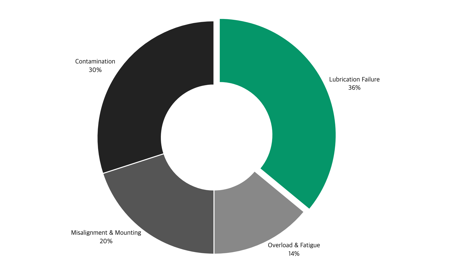
This chart reveals that lubrication-related issues alone account for over one-third of all premature bearing failures, making grease condition the single most impactful diagnostic target. Combined with contamination at 30 percent, lubricant and cleanliness management together address 66 percent of all failure causes. A structured grease assessment protocol and improved sealing practices, without any changes to equipment design or operating parameters, can eliminate two-thirds of the failure risk.
II. Failure Mode Identification from Wear Patterns
The wear pattern on a failed bearing is the most reliable indicator of the failure mechanism. Each mechanism produces distinctive marks on the raceways, rolling elements, and cage. The key is to examine the bearing immediately upon removal, before cleaning or handling obscures the evidence. Photograph the bearing from multiple angles before disassembly.
Two categories of evidence matter most. Thermal evidence, meaning any discoloration ranging from straw yellow through dark blue to black, points toward lubrication practice because thermal damage in greased bearings almost always originates from insufficient lubricant film or excessive grease churning. Mechanical evidence, meaning spalling, pitting, and surface fatigue marks, indicates load-related or alignment-related failure mechanisms.
Figure 1. Bearing Wear Pattern Diagnostic Guide
Wear Pattern | Location | Appearance | Indicated Mechanism | Corrective Action |
|---|---|---|---|---|
Uniform dull finish on raceway | Full circumference, both rings | Matte, polished appearance | Abrasive wear (contamination) | Improve sealing, filter oil/grease |
Localized spalling | Load zone of outer ring | Flaking, crater-like pits | Fatigue (overload or end of life) | Check load rating, alignment |
Circumferential spalling | Full track on inner ring | Continuous flaking band | Misalignment or shaft deflection | Check alignment, coupling condition |
Discoloration (blue/brown) | Rolling elements and raceway | Heat tint, temper colors | Thermal damage (over-greasing, insufficient lubrication, or overload) | Check lubrication practice, load |
Corrosion pitting | Random on raceway surface | Red-brown pits, rough texture | Moisture contamination | Improve sealing, check storage conditions |
Cage wear/breakage | Cage pockets, rivets | Worn pockets, cracked cage | Lubrication failure or vibration | Check grease condition, mounting |
Brinelling (true) | Regular spacing in raceway | Indentations matching roller spacing | Impact loading during installation | Improve mounting procedures |
False brinelling | Shallow marks in raceway | Slight depressions with polished bottoms | Vibration during standstill | Apply anti-fretting measures |
This diagnostic table enables rapid identification of the primary failure mechanism from the physical evidence. The critical distinction is between thermal discoloration, which points to lubrication issues, and spalling patterns, which point to mechanical causes. A common error is attributing thermal damage to overload when the actual cause is over-greasing. Overload-induced thermal damage concentrates in the load zone, while over-greasing thermal damage appears uniformly around the full circumference because churning heats the entire cavity.
If thermal discoloration is present, proceed to the grease condition assessment in Section III. If spalling is the primary finding, shift to load analysis and alignment verification. When both thermal and mechanical evidence coexist, the thermal damage is typically the primary cause, because elevated temperatures soften bearing steel and accelerate spalling under loads that would otherwise be within the design envelope.
III. The 10-Minute Grease Condition Assessment
When the wear pattern suggests lubrication failure, the condition of the grease provides the next level of diagnostic information. This assessment can be performed in the field with no special equipment and takes approximately 10 minutes, covering three dimensions: visual characteristics, tactile properties, and quantity in the housing.
Visual Assessment (2 minutes)
Remove a sample of grease from the bearing housing or from the bearing itself during disassembly. Place the sample on a clean white surface for consistent color evaluation.
Color: fresh grease retains its original color, typically light brown, red, blue, or white. Darkened or blackened grease indicates thermal degradation or contamination with wear debris. A shift toward gray or metallic sheen indicates wear metal contamination. Milky or opaque grease that differs from its normal appearance suggests water contamination. Compare the used sample against a reference sample of fresh grease from the same product whenever possible.
Consistency: fresh grease maintains its original NLGI grade consistency. Most bearing greases are NLGI 2, which has the consistency of peanut butter at room temperature. Grease that has become hard, dry, or caked has lost its base oil through thermal evaporation or oxidation. Grease that has become runny, separated, or shows pools of free oil has undergone mechanical shear breakdown or water contamination.
Odor: a burnt petroleum smell indicates thermal degradation. A rancid or acidic smell indicates oxidation and acid formation, which can itself cause corrosive damage to bearing surfaces.
Tactile Assessment (1 minute)
Rub a small amount of grease between thumb and forefinger. Smooth, consistent texture indicates the grease is still functional. Gritty or sandy texture indicates particle contamination that is actively abrading the bearing surfaces. Even particles as small as 5 to 10 micrometers can initiate surface fatigue in bearing raceways. Watery or separated feel indicates water contamination or base oil separation.
Quantity Assessment (2 minutes)
Inspect the bearing housing fill level. An empty or nearly empty housing indicates under-lubrication, which is the most common cause of grease-related bearing failure. A housing packed completely full, with grease pressed against seals and extruded through gaps, indicates over-greasing. The optimal fill level for most bearings is one-third to one-half of the housing free space. During normal operation, grease forms a channel around the rolling elements, and the displaced grease serves as a reservoir that slowly feeds the contact zone. Overfilling eliminates the channeling space and forces continuous churning, generating heat with every revolution.
Decision Point
The combination of grease condition and quantity leads to one of three primary diagnoses. If the grease shows thermal degradation (blackened, burnt smell, hard or caked) and the housing is overfull, the diagnosis is over-greasing. If the grease shows contamination (gritty, metallic, water-separated) and the housing has adequate fill, the diagnosis is contamination ingression. If the housing is empty or the grease is severely depleted, the diagnosis is under-lubrication. Each diagnosis leads to a different corrective action, which is why the assessment must be performed before deciding on the repair approach. The 10-minute investment saves the weeks or months of premature bearing life that result from treating symptoms instead of causes.
IV. The Hidden Danger of Over-Greasing
Over-greasing is the most under-recognized cause of bearing failure because it seems counterintuitive that too much lubricant could damage a bearing. Yet over-greasing is responsible for a significant percentage of grease-lubricated bearing failures, particularly in electric motors and pump systems where automatic grease systems are installed. The problem is especially prevalent in plants that have transitioned from manual to automatic lubrication without recalibrating the delivered quantities.
The Thermal Runaway Mechanism
When excess grease fills the bearing cavity, the rolling elements must push through the grease on every revolution rather than rolling on a thin film. This churning action converts mechanical energy into heat. The temperature rise is immediate and measurable: field data shows that introducing a single excess stroke of grease into a bearing can raise the operating temperature from approximately 52 degrees C to 84 degrees C within 10 minutes (Reliable Plant, 2023).
In a bearing operating at 1,800 RPM with a correctly filled housing, the operating temperature might stabilize at 60 to 70 degrees C. The same bearing with an overfilled housing can reach 100 to 120 degrees C or higher (Bearing News, 2023). Unlike the temporary rise after normal relubrication that subsides within 20 to 30 minutes, the sustained elevation from chronic over-greasing persists because the cavity never reaches a stable, channeled state before the next relubrication event adds more grease.
At elevated temperatures, the base oil bleeds out of the thickener structure at an accelerated rate, leaving behind a dry soap residue that provides no lubrication. This creates a thermal runaway cycle: higher temperature causes faster base oil loss, which increases friction, which raises temperature further. Once the temperature exceeds the drop point of the thickener, typically 180 to 260 degrees C depending on thickener type, the grease structure collapses completely. At bearing temperatures between 120 and 150 degrees C, the bearing is likely in some stage of failure. Above 150 degrees C, failure can progress from initial damage to seizure in hours or minutes (Machinery Lubrication, 2023).
Recognizing Over-Greasing in the Field
Several indicators help identify over-greasing before catastrophic failure occurs. Grease purging from seals or shields is the most visible sign, though it is often dismissed as normal. In reality, grease being pushed out means internal pressure is exceeding the seal retention force. Elevated bearing housing temperature that does not correspond to process load changes points to grease churning. Unusually high motor current draw can indicate increased rolling resistance. Grease buildup around seals and drain ports confirms over-application.
Prevention Through Calculated Relubrication
The correct relubrication quantity can be calculated using: G = 0.005 x D x B, where G is the grease quantity in grams, D is the bearing outside diameter in millimeters, and B is the bearing width in millimeters. For a 6310 bearing (D = 110 mm, B = 27 mm), this yields G = 14.85 grams per relubrication event, approximately one tablespoon. Applying significantly more increases the risk of churning and thermal damage.
Automatic grease systems must be calibrated to deliver this calculated quantity at the correct interval. Their output should be verified periodically because pump wear, line restrictions, and fitting blockages can cause deviation from the set point.
V. Grease Selection Verification: Viscosity and Thickener Compatibility
Incorrect grease selection is a root cause that is often overlooked because the wrong grease may function adequately for weeks or months before its limitations cause failure. The mismatch only reveals itself when accelerated wear or thermal stress accumulates to the point of failure. Two selection parameters are critical: base oil viscosity match and thickener compatibility.
Base Oil Viscosity at Operating Temperature
The base oil in the grease provides the lubricating film that separates rolling elements from raceways. Its viscosity must be sufficient at the bearing's actual operating temperature, not just the reference temperature on the data sheet. The required viscosity is expressed as the kappa ratio: actual oil viscosity at operating temperature divided by the minimum viscosity required by the bearing according to ISO 281 (Tribonet, 2023).
A kappa ratio between 1 and 4 indicates the bearing is operating in the ideal lubrication regime, with values closer to 4 representing the optimal elastohydrodynamic film condition where bearing life reaches its theoretical maximum. Below kappa 1, metal-to-metal contact occurs on each revolution and wear rate increases dramatically. Below kappa 0.5, the lubricant film is insufficient to prevent significant surface damage and bearing life shortens substantially (Efficient Plant, 2020).
The most common selection error is using a grease with base oil viscosity specified for ambient temperature rather than operating temperature. A grease with ISO VG 150 base oil provides excellent film thickness at 40 degrees C, which is the standard reference temperature on most data sheets. But at 80 degrees C, the viscosity of that same oil may drop by 70 to 80 percent. If this reduced viscosity falls below the minimum required by the bearing, the kappa ratio drops below 1 and surface damage begins despite the grease appearing adequate on paper. Conversely, selecting an excessively high viscosity grease (ISO VG 460) for a high-speed bearing creates churning resistance that generates heat, paradoxically accelerating the very viscosity loss the thicker oil was intended to prevent.
NLGI Grade Selection
Beyond base oil viscosity, the consistency grade of the grease must match the application. The NLGI scale ranges from 000 (semi-fluid) to 6 (block-like solid). Most industrial bearing applications use NLGI 2, which provides a balance between staying in the bearing and releasing base oil to the contact zone. NLGI 1 is appropriate for low-temperature applications below minus 20 degrees C or for centralized lubrication systems where the grease must flow through long delivery lines. NLGI 3 may be selected for high-speed applications above 10,000 RPM or for vertical shaft bearings where a stiffer grease resists gravity-driven migration (NLGI, 2023). Selecting the wrong NLGI grade creates problems that mimic other failure modes: a grease that is too soft may leak out of the housing and appear to be a sealing problem, while a grease that is too stiff may not flow into the contact zone during startup, causing dry running damage that looks identical to under-lubrication.
Thickener Compatibility
Mixing greases with incompatible thickeners can cause the combined mixture to soften dramatically or to harden and fail to release base oil. Both outcomes lead to bearing failure, often weeks or months after the mixing event, making the connection between cause and effect difficult to establish.
Figure 2. Grease Thickener Compatibility Reference
Thickener | Lithium | Lithium Complex | Calcium | Calcium Sulfonate | Polyurea | Bentonite |
|---|---|---|---|---|---|---|
Lithium | Compatible | Compatible | Compatible | Compatible | Test Required | Incompatible |
Lithium Complex | Compatible | Compatible | Compatible | Compatible | Test Required | Incompatible |
Calcium | Compatible | Compatible | Compatible | Compatible | Incompatible | Incompatible |
Calcium Sulfonate | Compatible | Compatible | Compatible | Compatible | Test Required | Incompatible |
Polyurea | Test Required | Test Required | Incompatible | Test Required | Compatible | Incompatible |
Bentonite | Incompatible | Incompatible | Incompatible | Incompatible | Incompatible | Compatible |
The most critical rule from this chart is that bentonite (clay-based) grease is incompatible with all other thickener types and must never be mixed. Even a small amount of bentonite grease introduced into a bearing previously lubricated with lithium or polyurea grease can destabilize the entire mixture.
Polyurea greases deserve particular attention because their compatibility varies depending on the specific polyurea chemistry. Some polyurea formulations are compatible with lithium and lithium complex greases, while others are definitively incompatible. Even two greases labeled as "polyurea" from different manufacturers may not be compatible with each other (STLE, 2023). For any combination marked "Test Required," obtain compatibility test data from the grease suppliers before mixing.
When switching grease types, the safest practice is a complete purge of the old grease before introducing the new product. Run the bearing with excess new grease while allowing the old grease to purge out through the relief port, then drain back to normal fill level. Gradual displacement without a dedicated purge cycle leaves a mixed zone that may take dozens of relubrication cycles to fully clear (Machinery Lubrication, 2023).
VI. Relubrication Interval and Quantity: Getting Both Right
Even when the correct grease is selected, improper relubrication timing undermines bearing life. The interval between relubrication events must balance two competing risks: relubricate too infrequently and the grease degrades past its useful life. Relubricate too frequently and excess grease accumulates, creating the over-greasing condition described in Section IV.
Factors That Determine Relubrication Interval
Grease life in a bearing is governed primarily by temperature, speed, and the operating environment. Temperature has the strongest influence: grease service life halves for every 15 degrees C increase in operating temperature above the grease's rated baseline (SKF, 2023). A grease rated for 10,000 hours at 70 degrees C may last only 5,000 hours at 85 degrees C and 2,500 hours at 100 degrees C. This exponential decay means that operating temperature must be measured, not assumed, when setting relubrication intervals.
Speed influences grease life through mechanical shear on the thickener structure. The speed factor, expressed as the product of the bearing mean diameter (dm in mm) and the rotational speed (n in RPM), provides a standardized measure. Bearings with speed factors (n x dm) above 300,000 require shorter intervals and often benefit from greases formulated for high-speed service with enhanced shear stability. Environmental contamination acts as a multiplier on baseline degradation rates. In severe contamination environments, the relubrication interval may need to be reduced by 50 percent or more compared to clean-environment baselines.
Calculating the Correct Quantity
The relubrication quantity formula G = 0.005 x D x B provides the baseline grease amount per relubrication event. Grease should be applied slowly, ideally while the shaft is rotating, to allow new grease to displace degraded grease from the contact zone. A drain plug or relief valve on the bearing housing is essential for preventing accumulation over multiple relubrication cycles.
VII. Key Takeaway
Bearing wear patterns are the most reliable diagnostic indicator: thermal discoloration points to lubrication failure, uniform dull finish points to contamination, and localized spalling points to mechanical overload. Accurate pattern reading prevents repeat failures caused by addressing the wrong root cause.
The 10-minute grease condition assessment provides the field-level data needed to distinguish between under-lubrication, over-greasing, and contamination without laboratory analysis. Perform this assessment on every failed bearing before deciding on the corrective action.
Over-greasing causes thermal runaway through grease churning, ending in base oil loss and bearing seizure. The relubrication quantity formula (G = 0.005 x D x B) prevents this failure mode. A bearing housing should never be more than half full.
Base oil viscosity must be verified at the actual operating temperature. The kappa ratio must remain between 1 and 4. A grease that appears adequate on the data sheet can provide insufficient lubrication if the operating temperature is 30 to 40 degrees C above the viscosity rating condition.
Grease thickener incompatibility causes mixture softening or hardening. Bentonite greases are incompatible with all other types. Polyurea compatibility varies by manufacturer chemistry. When switching grease types, purge completely.
Relubrication intervals must account for operating temperature, speed factor, and environmental contamination. Grease life halves for every 15 degrees C increase above the rated baseline.
Lubinpla's Assistant can cross-reference your bearing specifications, operating conditions, and current grease selection to verify base oil viscosity at your actual operating temperature, calculate the correct relubrication quantity and interval, and flag thickener compatibility risks across your equipment fleet.
VIII. References
[1] Reliable Plant, "12 Reasons Why Bearings Fail", 2023. https://www.reliableplant.com/Read/30255/reasons-bearings-fail
[2] Machinery Lubrication, "Lubricant Failure = Bearing Failure", 2023. https://www.machinerylubrication.com/Read/1863/lubricant-failure
[3] AST Bearings, "Bearing Failure Analysis", 2023. https://www.astbearings.com/failure-analysis.html
[4] Bearing News, "The Most Common Causes of Bearing Failure and the Importance of Bearing Lubrication", 2023. https://www.bearing-news.com/the-most-common-causes-of-bearing-failure-and-the-importance-of-bearing-lubrication/
[5] Machinery Lubrication, "Grease Compatibility Chart and Reference Guide", 2023. https://www.machinerylubrication.com/Read/1865/grease-compatibility
[6] Machinery Lubrication, "How to Determine Grease Compatibility and Why It's Important", 2023. https://www.machinerylubrication.com/Read/30727/determine-grease-compatibility
[7] STLE, "Grease Compatibility", 2023. https://www.stle.org/files/TLTArchives/2023/05_May/Feature.aspx
[8] FlowFuse, "Preventive Maintenance in Manufacturing: Avoid Multi-Million Dollar Equipment Failures", 2025. https://flowfuse.com/blog/2025/09/preventive-maintenance-equipment-failure/
[9] Tribonet, "How to Determine Optimal Base Oil Viscosity for Rolling Bearings Using the ISO 281 Kappa Factor", 2023. https://www.tribonet.org/news/general-topics/how-to-determine-optimal-base-oil-viscosity-for-rolling-bearings-using-the-iso-281-kappa-factor/
[10] Efficient Plant, "Know Your Kappa Values", 2020. https://www.efficientplantmag.com/2020/06/know-your-kappa-values/
[11] SKF, "Grease Life and Relubrication", 2023. https://www.skf.com/group/products/rolling-bearings/principles-of-rolling-bearing-selection/bearing-selection-process/lubrication/grease-life-and-relubrication
[12] NLGI, "FAQs", 2023. https://www.nlgi.org/faqs/
[13] Machinery Lubrication, "How to Manage Hot Bearings in Your Plant", 2023. https://www.machinerylubrication.com/Read/30608/manage-hot-bearings
Powered by Lubinpla
Discover how technical teams solve complex challenges faster with AI.